Table of Contents
Component List
The following components are required. Some can be omitted depending on your requirements.
- Micro SD card; 16GB or less recommended * * *
- x2 ESP32-DevKitC V4 with ESP32-WROOM-32U
- ATGM336H GPS/GNSS module with antenna
- Mini Micro SD Card reader/writer SPI*
- SIM800L Module with spring antenna* and 85c zener diode * * (optional, needed for GSM)
- 0.91“128×32 i2c LCD 3.3v (optional, recommended)
- DS18B20 temperature sensor with 4.7k resistor (both optional)
- Plastic enclosure, at least 100x60x25mm* (3.94”x2.36“x0.98”)
- 2x IPEX → SMA (or RP-SMA) cables
* This component doesn't seem to have an exact accurate part number, please read the buying guide below.
* * The diode simply lowers the voltage so the SIM800L can be powered from 5v but only receive 4.4v or less. Any diode can be used if the voltage drop is high enough.
* * * Micro SD cards which are 32GB may have compatibility issues. Please use a 16GB card if possible.
This device is powered externally; I recommend buying a USB powerbank if you do not already have one. A 5200mAh battery will give you a good balance between portability and runtime.
The PCB
To financially support the project, I recommend purchasing an official PCB. The PCB design files are open source so you can arrange your own fabrication if desired.
Click here to view the PCBs for sale on Tindie.
Buying Guide
ESP32 Boards
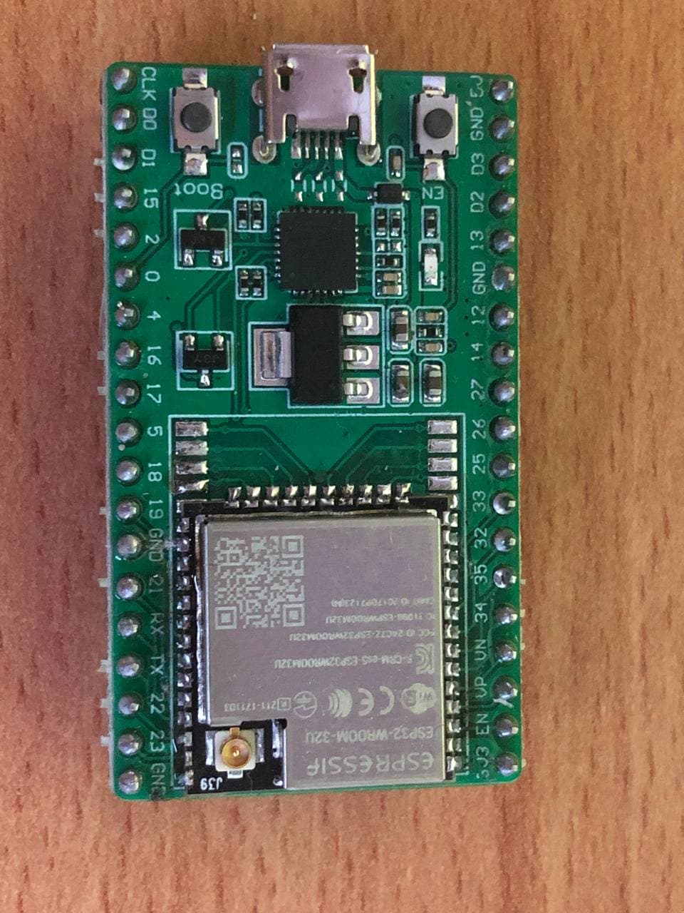
Your ESP32-DevKitC V4 should have an ESP32-WROOM-32U chip. The board should have 19 pins on each side and the pinout should match this image:
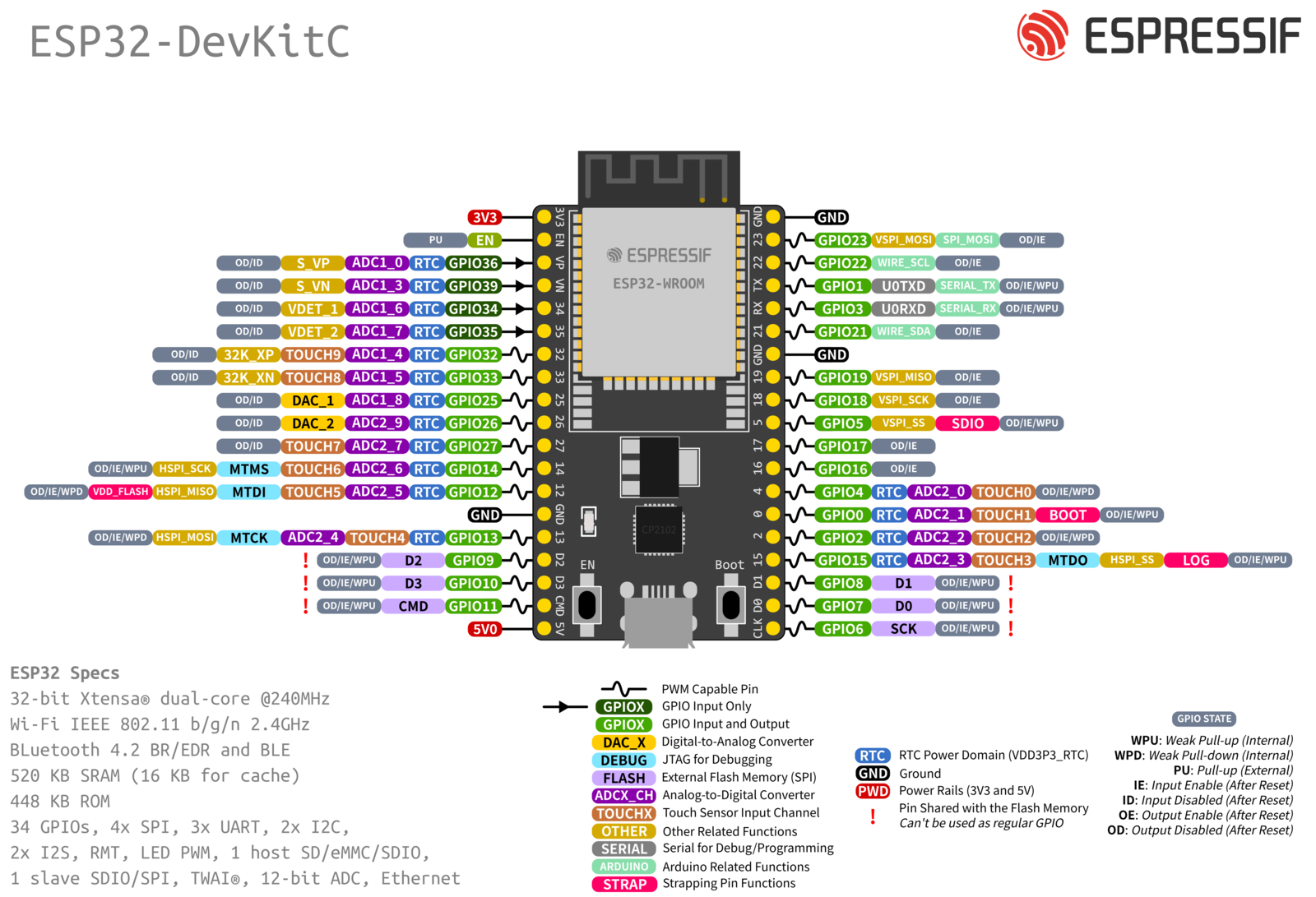
Also see this pinout taken from the espressif ESP32 devkit v4 page
If you hold the board with the USB port and 2 buttons at the top (facing you), the top right pin should be 5v. The bottom right pin should be 3.3v and the bottom left pin should be ground. Be sure to buy a board which can take an external antenna (it should not have a PCB antenna at all)
GPS/GNSS module
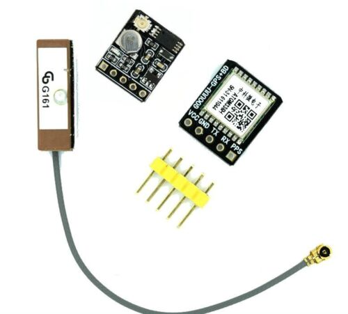
Your ATGM336H GPS/GNSS module should have 5 pins and measure approximately 12mm by 15mm (0.47“ by 0.59”). The pins should be in this order: VCC, GND, TX, RX, PPS. You should get an external antenna with your module. It should look like this:
You must remove the PPS header from your module before soldering to the PCB. Read the Assembly Instructions page for more information about pinheader requirements. I recommend buying a GNSS module which does not come with a pre-soldered pinheader if possible.
Micro SD card reader
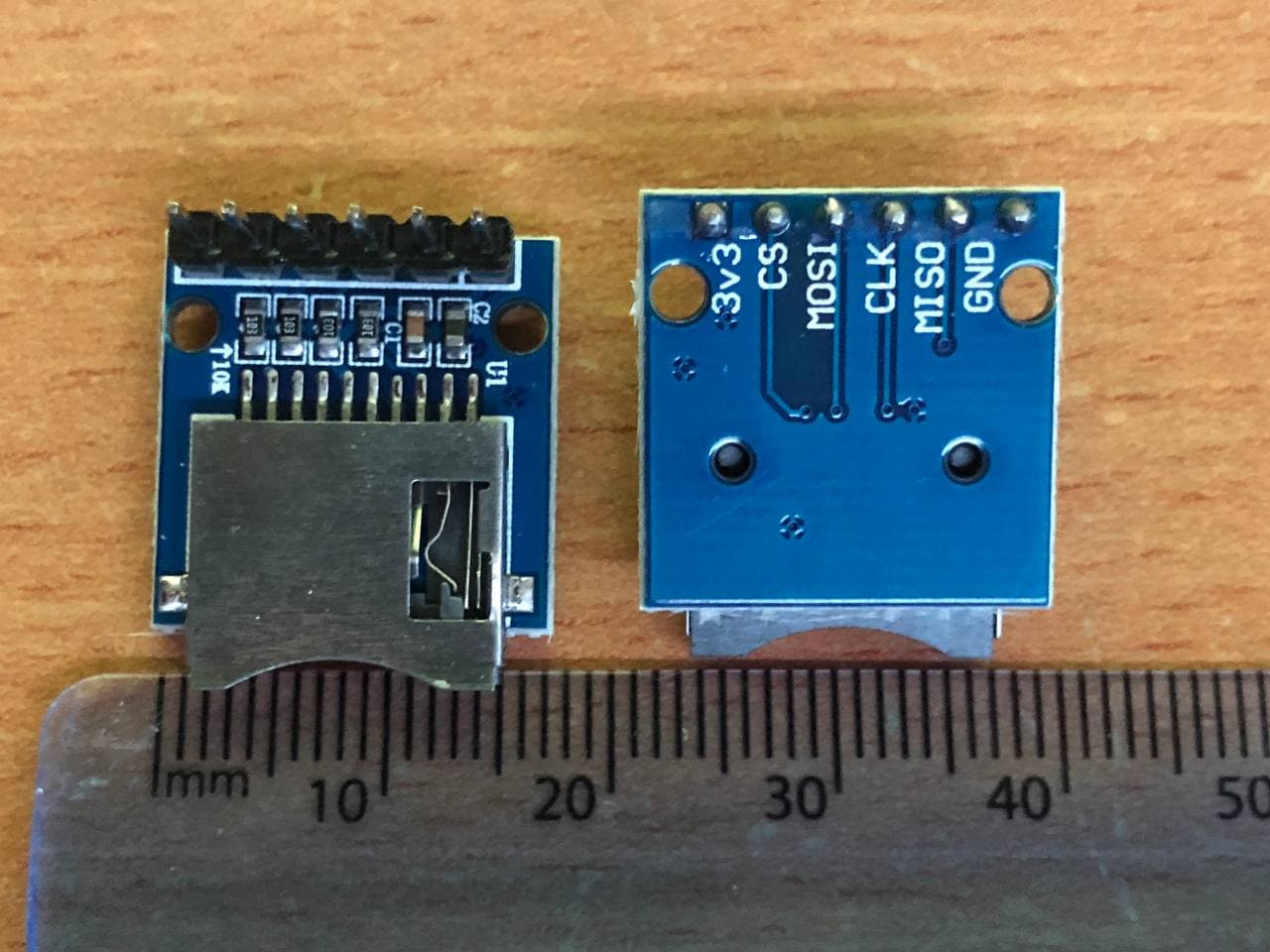
Your Mini Micro SD Card reader/writer needs to be SPI and the pins should be in this order: 3v3, CS, MOSI, CLK, MISO, GND. The dimensions should be approximately 17mm by 17mm (0.67“ by 0.67”) with a small overhang for the card holder. It should look like this:
SIM800L module
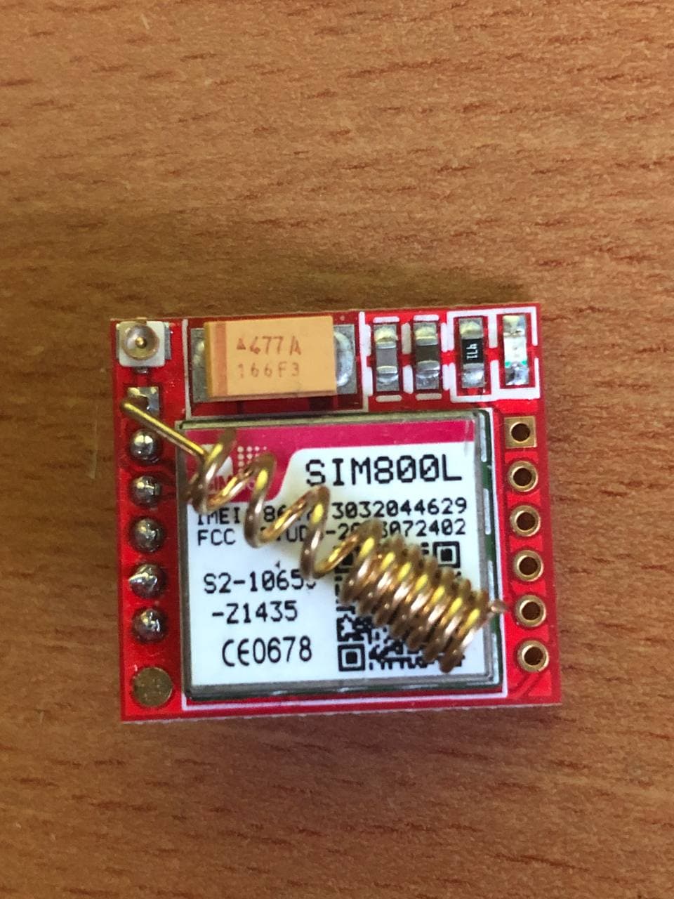
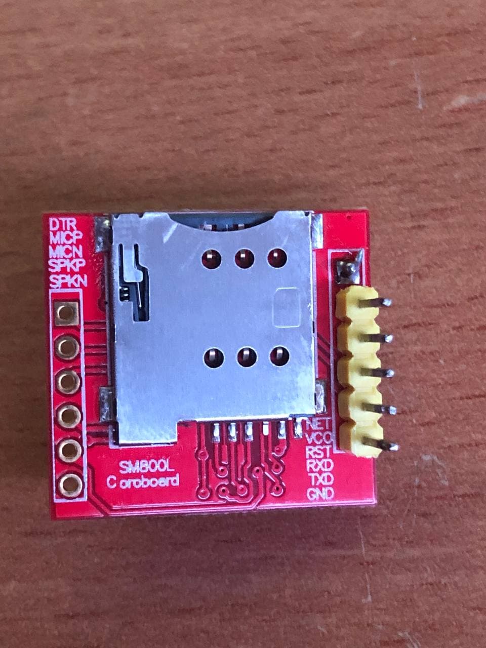
The SIM800L “coroboard” Module should be the mini/small development board type with 6 pins on both sides. Only the pins on one side are used and they should be in this order: Net/Ant, VCO/VCC, RST, RX(D), TX(D), GND. It should look like this:
The dimensions should be approximately 23mm by 24mm (0.91“ by 0.94”). I personally use the antenna which looks like a spring soldered to the PCB, many sellers will include this. External antennas are also possible but I haven't tested the placement of one in my portable wardriver before.
i2c LCD
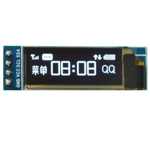
Your 0.91“128×32 i2c LCD should be approximately 29mm by 11mm (1.14” by 0.43“). The pin order does not matter as long as it has SCL and SDA (i2c) in addition to 3.3 volt power. The LCD I am using has the SSD1306 driver so theoretically any SSD1306-based i2c display will work fine (even different sizes). This display will connect to the PCB with a wire that you solder on which is why the pin order does not matter. Mine looks like this:
DS18B20 Sensor
The DS18B20 temperature sensor should be the 3-leg component only; no wires or boards should be included with it. You'll also need a 4.7Kohm through-hole resistor for it to work.
Enclosure
Recently the community has published various 3D printed designs for wardriver.uk enclosures. For example, this enclosure by @Barry_73601 or this one by @Gavin_302163 might be a good choice. Alternatively a generic box from Aliexpress or ebay will work.
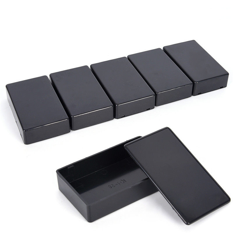
There are lots of plain black plastic enclosures available on ebay which are 100x60x25mm. This project was designed to fit in this specific enclosure but it is a tight fit. An enclosure slightly bigger than this might be easier but could make it less portable. Some of these boxes contain standoffs in the corners which may need to be removed. The enclosures I use look like this:
You will need to drill holes for the wires, display, and external antennas.
Once you have your components, check out the Assembly Instructions page.


