Table of Contents
Assembly Instructions
Introduction
These instructions are for the 3rd revision of the Wardriver. Please ensure you have the components listed on the Component List page.
If you have the WiSpy kit by hackerboxes.com, please instead follow the WiSpy HackerBox 0089 build instructions.
For ease of assembly, this project is entirely through-hole and doesn't require any surface-mount soldering. It should be reasonably easy to assemble for people with only a few hours of soldering experience.
I recommend following this guide in order. The PCB contains text which indicates which component goes where; most of this text will be deliberately covered up by the components once they are soldered. For example, your SIM800L module will cover up the word “SIM” on the board.
Also see the Wiring and Connections page for connection details if you are building without a PCB.
Both ESP32 boards remain programmable after being soldered into the PCB. You can flash them before or after assembly. I recommend testing them before soldering because they are difficult to remove once fully soldered.
Temperature Sensor
This is optional. If you don't want temperature data, you can skip this step.
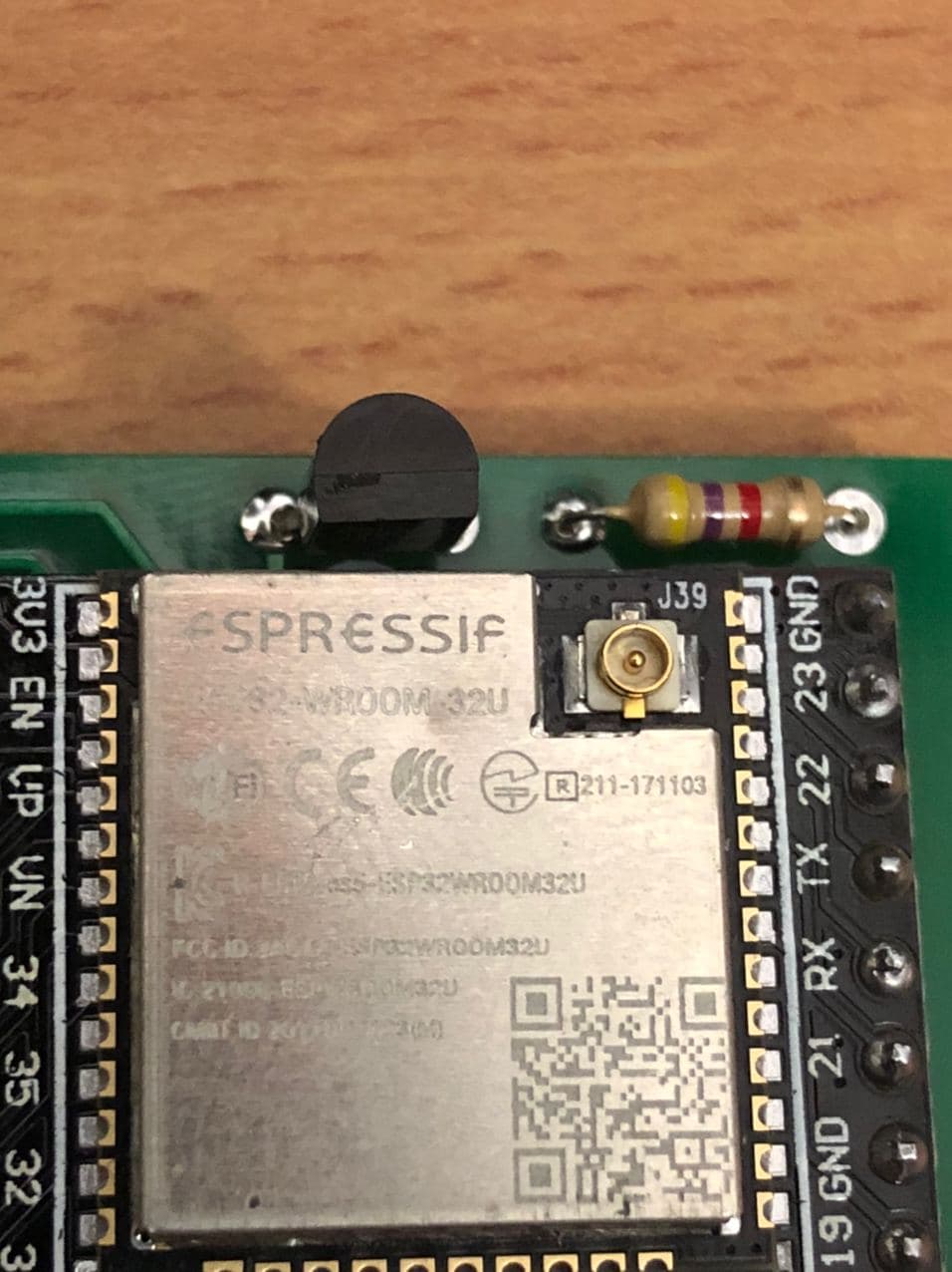
The temperature sensor is soldered to the top-side of the PCB near the text “Made by Joseph Hewitt”. Look out for a large “D” character which shows the orientation of the DS18B20 temperature sensor.
The orientation of the DS18B20 sensor can be determined by looking at the “D” on the PCB where the flat edge of the DS18B20 should match the flat edge of the “D”. The curved edge of the sensor should face towards the outside of the PCB. For reference, here is the temperature sensor on my test wardriver:
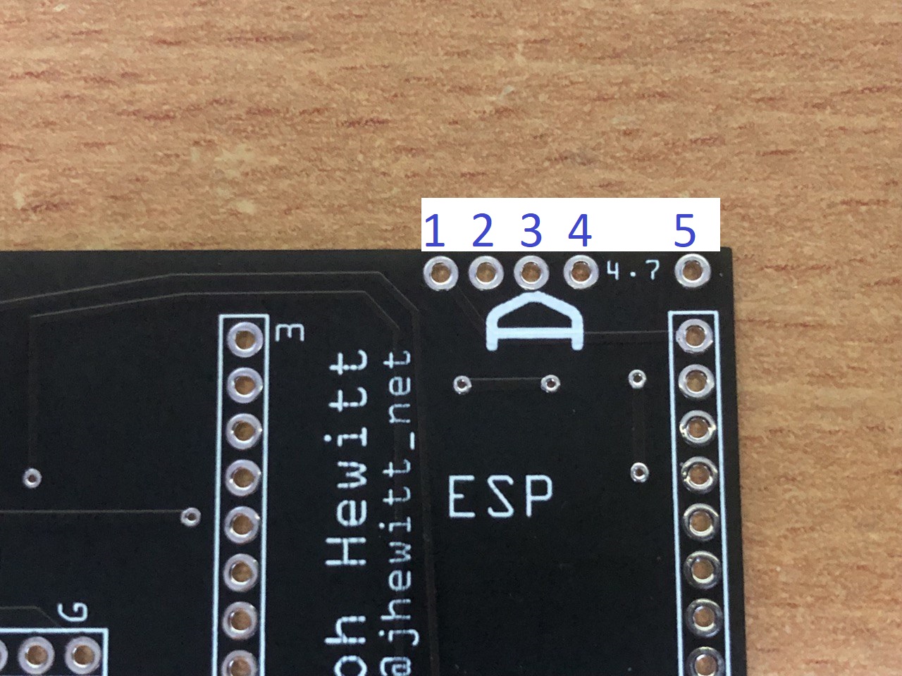
This image shows the pins required for the DS18B20 and the resistor:
Pins 1, 2, and 3 are for the DS18B20. Pins 4, and 5 are for the resistor.
Once both the DS18B20 and the 4.7K resistor are soldered, move onto the next step.
GPS
Please read this whole section fully before soldering the header onto your GPS module.
Before soldering, you should remove the pin in your header belonging to “PPS” on the GPS. This is unused and could cause a short circuit to the SIM800L.
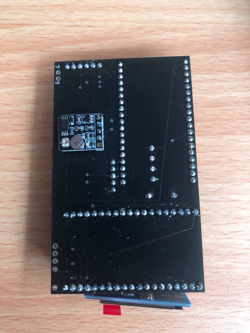
The GPS module should be soldered to the bottom/back of the board where the text “GPS” appears. A “3” and a “G” is written next to the pins to indicate 3.3v and ground; use this to ensure your orientation is correct. Your GPS module should cover up the text “GPS” and the module should “point” towards the edge of the PCB. The GPS antenna connector should be facing away from the PCB.
This image shows the GPS module soldered onto the PCB:
Micro SD Card Reader
Solder the Micro SD card reader to the section of the PCB marked “SD” using the “3” and “G” to confirm 3.3v and ground is orientated correctly. I recommend soldering this component with an SD card already inserted; this allows you to be certain the pins from the GPS module will not get in the way. I also recommend soldering the SD card reader with a slight upwards angle to make it easier to remove the card when everything is assembed.
SIM800L Module
The SIM800L is optional and only required if you want to capture GSM cell tower information
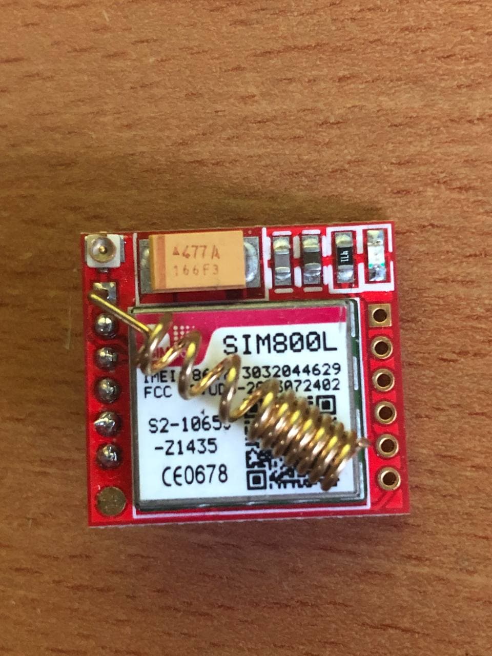
Only 1 row of SIM800L pins are in use so you do not need to solder both pinheaders. Only the row containing these pins needs to be soldered: VCO/VCC, RST, RX(D), TX(D), GND.
You should solder the spring antenna onto the module in the Net/Ant hole first. I suggest that you solder the spring antenna diagonally across the SIM800L chip itself like so:
Place your SIM800L module into the PCB at the position marked “SIM”. Please ensure the metal part of the SIM card holder does not come into contact with any of the GPS pins. Your module should fully cover the word “SIM” on the PCB.
It is normal for the SIM800L module to overhang the PCB slightly.
LCD and Diode
Your LCD is connected via 4 i2c pins (3.3v, Ground, SCL, and SDA). On the official PCB, these are underneath one of the ESP32 boards.
Start by soldering 4 wires onto your LCD; you need to decide the length of the wire yourself based on how far the LCD will be from the PCB in the enclosure. I usually use ~6cm wires to get from the PCB to the front of the enclosure. Now solder the 4 wires onto the PCB pins labelled 3, G, SCL, and SDA. 3 is 3.3v and should connect to VCC/3.3 on your LCD. G is ground, SCL and SDA should match the pins on your LCD (eg, SDA → SDA, SCL → SCL)
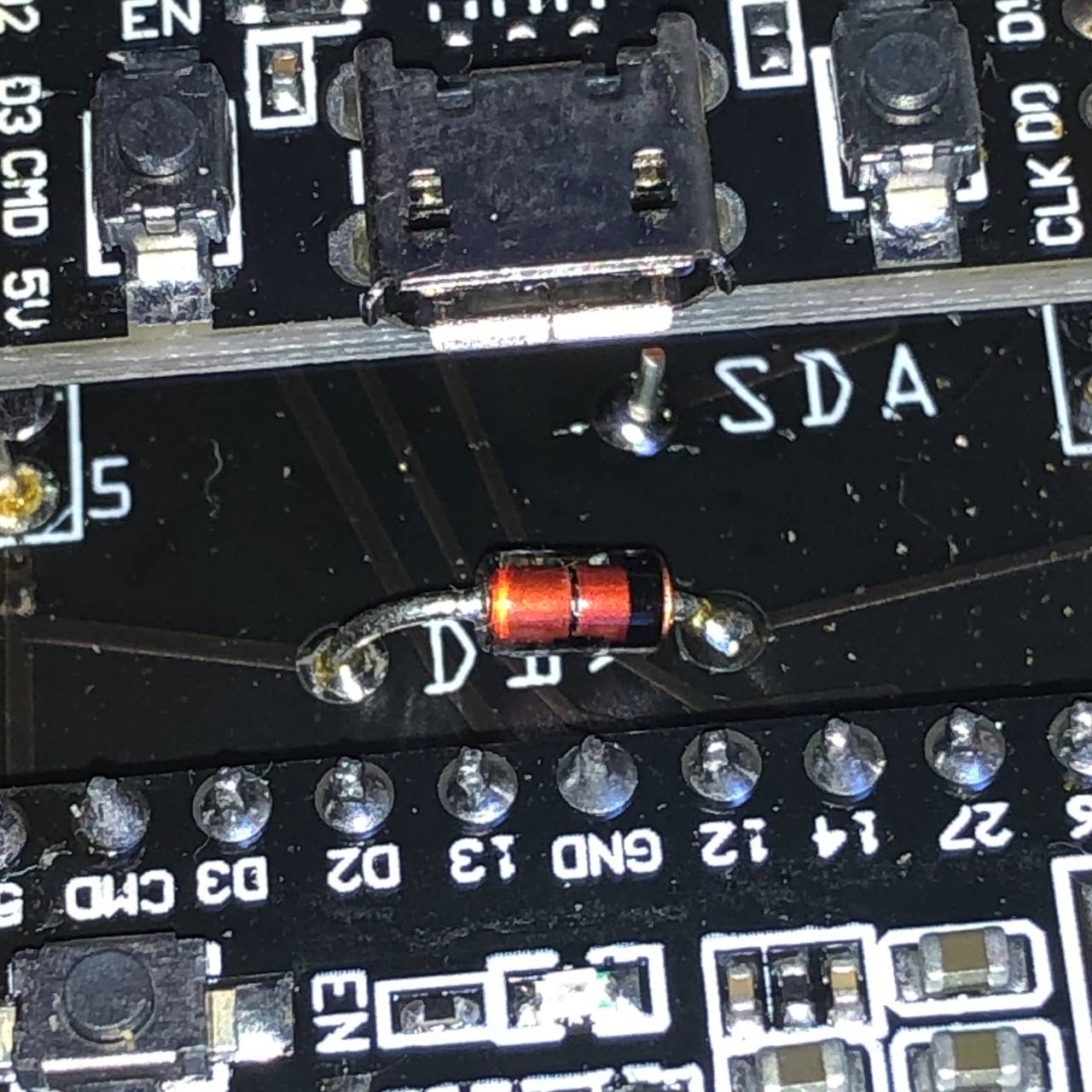
Now solder your diode into the section labelled “D1” (only required if using the SIM800L for GSM support). The polarity is determined by the “>” symbol between the pins on the PCB where the point indicates the cathode (the black line on the diode). See this image for further clarification:
ESP32 Boards
The orientation of the ESP32 boards can be determined by looking for “ESP” written on the PCB; this denotes the position of the large silver ESP32 chip on your board. Alternatively, you can match the 5v and 3v pins on your ESP32 board to the “5” and “3” written on the PCB.
You should solder the bottom ESP32 board first (the one which covers up the text “Made by Joseph Hewitt”) and ensure the board is pushed into the PCB as far as it can possibly go. It may be a tight fit and you may have to slightly bend some pins.
You should not push the top ESP32 board fully into the PCB; if you do, you will make it much harder to access the USB port because it will be partially blocked by the other board. I suggest connecting a USB cable to the top ESP32 board before pushing it into the PCB so you can get the right level of clearance. You should also be mindful of how “tall” you make the wardriver otherwise it may not fit in the enclosure.
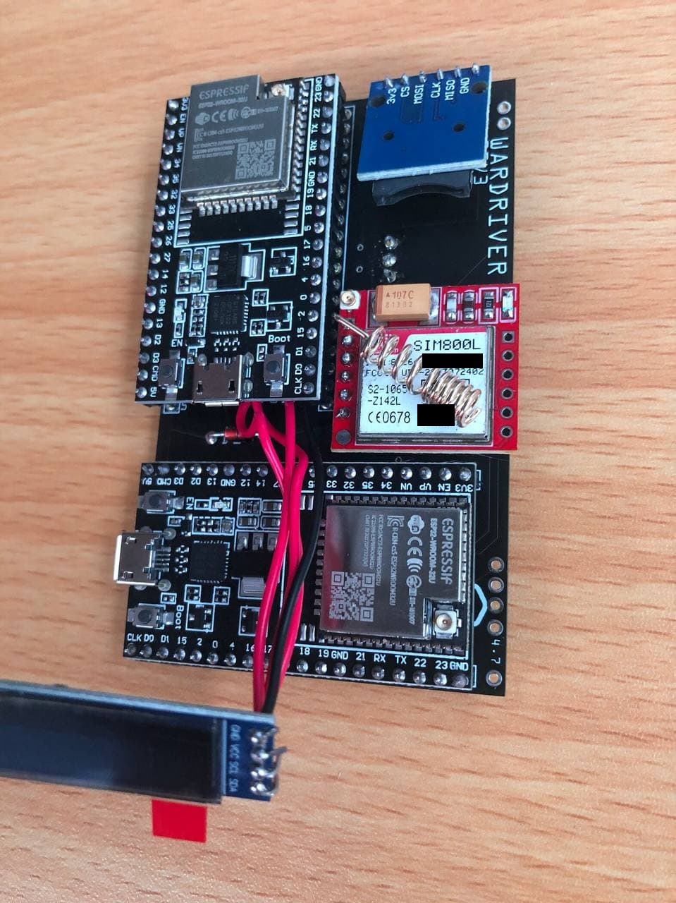
Once all components are soldered, your board should look similar to this:
Note: This image is of a wardriver which doesn't include the DS18B20 temperature sensor - this is an optional component.
In my experience, putting the GPS antenna on or very close to an ESP32 will cause GPS lock issues. A distance of just 1-2cm is usually enough to resolve this problem. Many GPS antennas are directional so you should check which way is “UP” and position that side so it faces any wall of the enclosure without any PCB/components between.
Power Pins
The official Wardriver Rev3 PCB contains 2 power pins labelled “G” and “5”. These denote Ground and 5v and are connected directly to the power on the ESP32 boards. You can optionally solder wires here to power your Wardriver with an external regulated 5v power supply.
Alternatively, you can power your Wardriver by connecting a USB cable to one of the ESP32 boards.
Enclosure
Once all of the previous steps are complete, you should be able to mount your wardriver into the enclosure. I recommend testing your wardriver now before proceeding.
You will need 2 IPEX → SMA cables so you can expose SMA connectors on the outside of the enclosure for your antennas.
The enclosure needs 2 holes drilling for the WiFi antenna connectors, a hole for the power cable, and a large hole for the LCD. The exact placement of the antenna connector holes and LCD can be decided by you. The easiest way to power the wardriver is to use one of the USB ports on the ESP32 modules; one of these should touch the edge of the enclosure when placed inside - mark this as the location for the first drill hole.
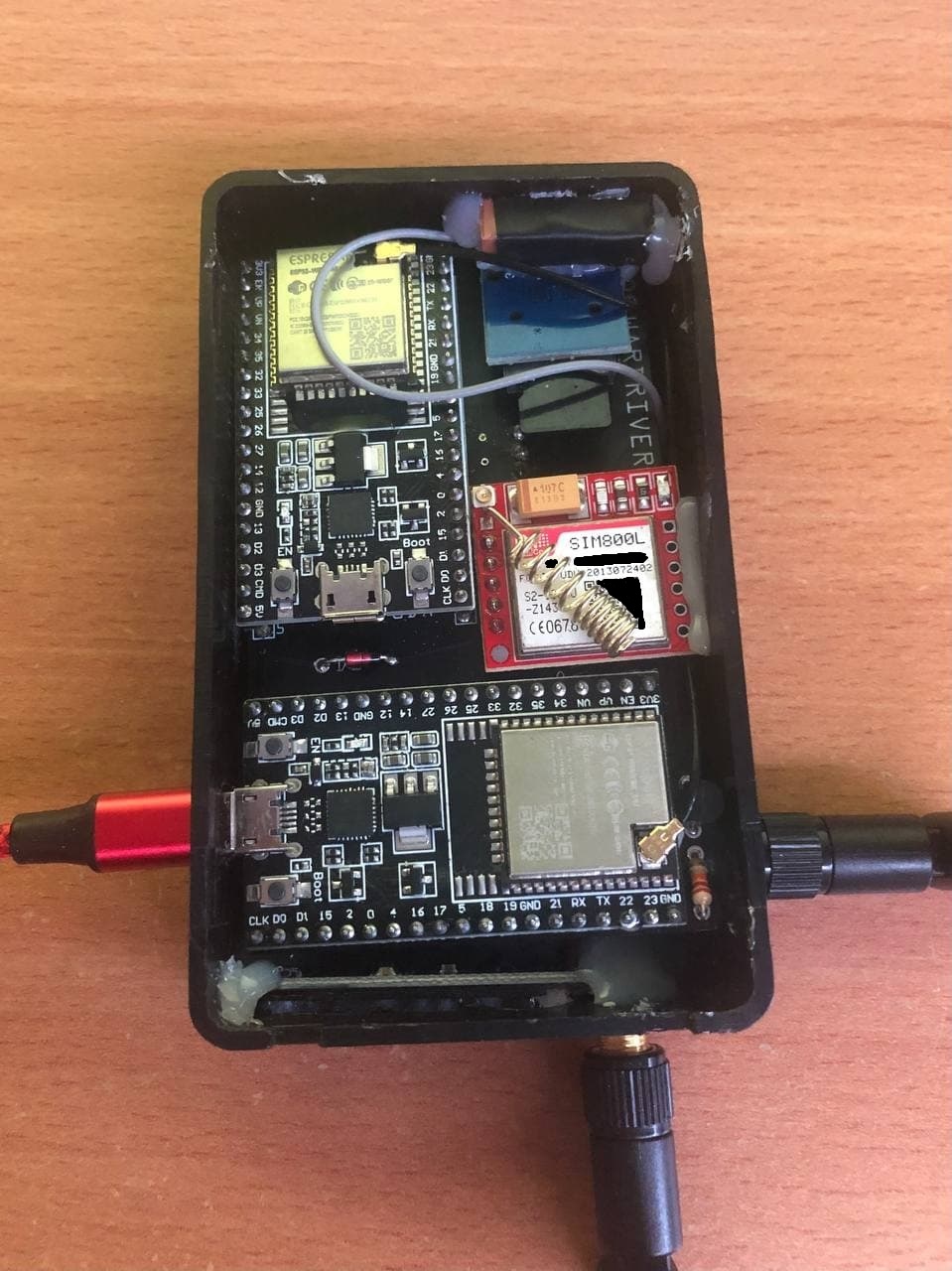
This image shows my preferred way to mount everything:
I personally drill a hole on the left edge to line up with ESP32 USB connector, then I make a hole at the front of the enclosure which is large enough to view the LCD through. I put one of my antenna connectors next to the LCD and the second connector opposite the USB power cable. The GPS antenna should remain inside and I generally glue it to the top of the SD card reader module.
This configuration allows me to use the wardriver in my back jeans pocket with the LCD and antennas pointing upwards out of my pocket. Your preferences may be different so it is okay to place your antennas and LCD in different locations.
The right-side edge should contain a gap between the PCB and the enclosure wall big enough to route wires if needed.

